JEOL JXA-8200 Imaging
The Jeol 8200 imaging system is computer controlled using the OS-9 computer system and is most conveniently run using the OS-9 monitor.
The operation of the Jeol imaging system is covered in the JEOL Control and Display document, paper copy only in the lab.
The following guide can be used to perform routine imaging tasks, but requires that you understand where the menus and buttons are located as described in the Jeol OS-9 Digital Imaging System manual.
Setting Up for Digital Imaging and Photography
The following sequence should be used or verified before you can acquire digital images.
- Samples already in the microprobe and vacuum has recovered so that electron beam is stable. Vacuum level should be ~ 1x10⁻³ Pascal in sample chamber.
- High voltage turned on, confirmed from green color square in uppler left corner of OS-9 monitor or pink colored button for HV in EOS Monitor windowkl.
- Filament saturated (Experienced users only, use EOS monitor to set saturation).
- Column aligned if necessary.
- Probe current for an imaging run is set using EOS Monitor CL lens button.
There are two probe current ranges to consider, trading or balancing spatial resolution vs. signal quality:
- Increased spatial resolution at decreased backscattered-electron sensitivity. Use 5-10 nA for high magnification and good resolution requirements.
- Increased BSE sensitivity at decreased spatial resolution. Use 25nA for compatibility with analytical runs that use 25nA probe current. Use 10-40nA for good backscattered-electron signal (but note beam sensitive materials require lower probe current).
- Choose a feature that has both x and y components of contrast, i.e., a set of cracks or pits with detail.
- Set optical focus using joystick arrows and reflected light monitor with reflected light turned on.
- Focus and stigmation checked at selected probe current
- Typical vacuum (not using liquid nitrogen trap) ~ 1x10⁻³ Pascal, dashed green line.
- Typical vacuum (using liquid nitrogen trap) ~ 1x10⁻⁴ Pascal, solid green line.
Vacuum levels during and after sample exchange:
- During and after sample exchange, the specimen chamber vacuum will be in the 10-2 Pascal range but will recover to 10-3 Pascal range. This is the orange region during sample exchange, with recovery below pink line within 15 minutes.
- Also, the blue ratemeter strip labelled "PIG3 1st DP Back" should recover and disappear within 30 minutes; if not contact Carpenter.
Abnormal specimen chamber vacuum levels:
- If there is a vacuum leak or samples with excessive outgassing have been put in the microprobe, the specimen chamber vacuum will stay in the upper 10-3 to 10-2 Pascal range. This is near or above the pink line, and this vacuum level is undesirable and should be remedied -- remove outgassing samples and/or see Carpenter.
Electron gun vacuum levels:
- The electron gun vacuum should be very stable when the SIP ion pump is used (LaB6 mode selected, typical condition) and should have a vacuum of ~ 1x10⁻⁵ Pascal, blue line.
- If the SIP ion pump is not used (W mode selected, not typical condition) the gun vacuum will not be as stable and should have a vacuum of ~ 1x10⁻⁴ Pascal, variable region of higher pressure above blue line.
JEOL 8200 Column Front Panel
The front panel of the microprobe column has the hardware interface for the vacuum system: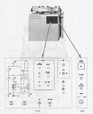
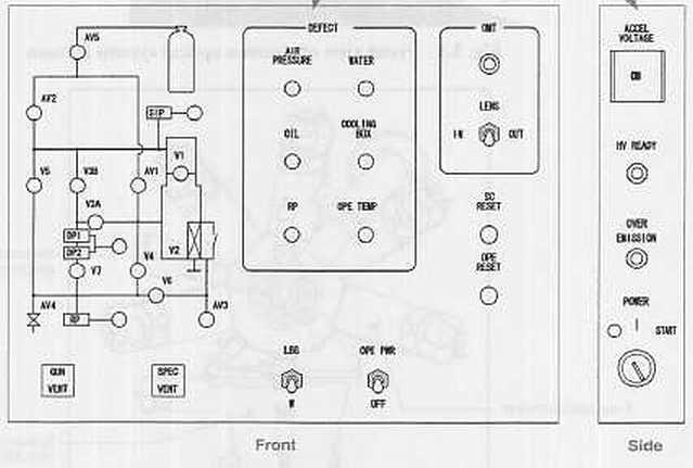
JEOL 8200 Column Front Panel: Vacuum System and Pump-down Controls
The front panel has three sections and a fourth section on the side panel of the column. The left panel has a diagram of the vacuum logic system which shows the valves that are open which are illuminated green. A valve that is closed is not illuminated.
Below the vacuum valve diagram are two push buttons that are used for venting the gun (Gun Vent) and the entire microprobe column (Spec Vent). The gun vent push button is used to vent the electron gun when the filament is to be changed, and only the gun is vented. The spec vent push button is used to vent the entire microprobe for maintenance purposes.
These vent buttons are not used for sample exchange or any of the routine procedures.
JEOL 8200 Column Front Panel: Defect Light Panel, Filament Mode, and OPE Pwr Switch
The center portion of the panel has defect lights that are illuminated when a defect condition is detected for:
- Air pressure defect: insufficient pressure from the dry nitrogen supply (nominally 60 psi), indicates nitrogen tank is empty and valves cannot be opened for sequencing.
- Oil defect: silicone oil is used to cool the magnetic lenses and if a leak occurs or the pump fails then a temperature sensor detects an oil coolant problem.
- RP defect: if the roughing pump belt breaks this defect light is illuminated. Note that our microprobe uses a direct drive scroll pump so we will not see this.
- Water defect: illuminated if an interuption of the chilled water supply has occurred. This will shut the microprobe off within about 5 minutes.
- Cooling box defect: a general defect problem in the cooling box system that is behind the microprobe.
- OPE Temp defect: high temperature sensed in the power supply that drives the high voltage and computer system in the microprobe console.
The OPE Pwr switch supplies power to all of the 8200 computer boards in the column and also turns on the high voltage supply. It must be on for the microprobe to be able to generate an electron beam. There are times when the computer loses communication and recycling of the OPE Power switch is necessary.
JEOL 8200 Column Front Panel: Transmitted Light Periscope and Reset Switches for SC and OPE
The right hand side of the front panel has a switch for the transmitted light periscope to be inserted or retracted. Our microprobe does not have this attachment.
The SC Reset and OPE Reset switches are in principle used to perform a hardware reset of the system command (SC) board and the operations power (OPE) systems. Generally, pressing these will guarantee that the OPE Power will have to be cycled anyway, so their use is not recommended, or rather, their use does not result in a solution to the computer lockup problem.
JEOL 8200 Column Side Panel: Accelerating Voltage Hard Switch, HV Ready Lamp, Master Power Switch
The side panel has the Accel Voltage push button located at the top. This push button is a hardware switch for the high voltage power and must be pushed in and illuminated in order for the microprobe system to turn on the high voltage supply via the software. Below this is the HV Ready indicator which is illuminated only when the microprobe has pumped to high vacuum and furthermore to the minimum vacuum level required for operation of the high voltage supply. The following is a summary of the requirements for producing an electron beam with the microprobe:
- The microprobe vacuum system must be turned on and the system pumps down to a vacuum level where high voltage can be turned on.
- The HV Ready light is illuminated and the HV ready message appears in the Vacuum window of the Jeol software.
- The Accel Voltage push button must be pushed in and illuminated (it is usually left in this position and all control is made using the software, but this is the master on/off switch for the high voltage).
- The high voltage is turned on using the software switch of the EOS Monitor application.
- The filament current is raised to the point of thermionic emission.
- The condenser lens is set for desired probe current, the objective lens is set for electron beam focus, the backscattered-electron or secondary-electron detector is turned on, and the imaging system is used, or X-rays are counted, etc.
Below the HV Ready lamp is the Over Emission indicator which generally indicates that too high of a gun bias has been used and that a dendrite or whisker has grown from the filament to thw whenelt (grid cap). This means that the gun has to be cleaned.
The Power switch is at the bottom of the panel and is used to turn the entire microprobe system on and off. The switch on our system is a three position switch with off in the lower position, on in the middle position, and start in the upper position. This switch is used for the following purposes:
- If the microprobe is currently turned off, the switch is moved to the full up position and released; this starts the vacuum system and will ultimately result in the microprobe at high vacuum with the HV Ready light illuminated.
- The microprobe is turned fully off by moving the switch to the full down position. This should only be done after the computers are all turned off.
- Clearing of a defect condition is handled by moving the switch to the full up position and releasing to the middle position.
JEOL 8200 Vacuum System: Sequencing Details
This section covers the details of valve sequencing for the JEOL 8200 during pump down. The valve configuration can be viewed in two places, the front panel display on the column, and the vacuum application (with "pressure" check box selected) in the JEOL software. The Probe for Windows Vacuum application can also display the vacuum levels without the valve information.
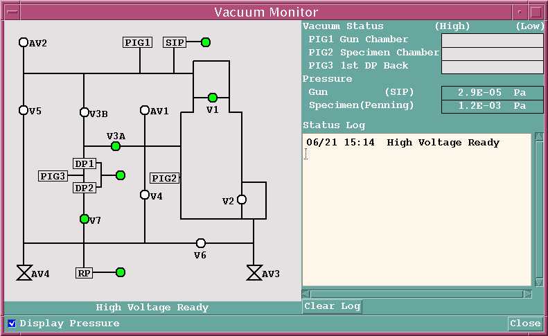
This is the normal high vacuum mode for the WU 8200 with the filament mode set to LaB6 mode, with the SIP ion pump turned on.
This display indicates that the instrument is at high vacuum and is at "High Voltage Ready" so that the accelerating voltage can be (or currently is) turned on.
The valves shown on this display are as follows:
- RP is the roughing pump. The light indicates that the pump is turned on.
- DP1 and DP2 are nominally the two diffusion pumps, on our system they are the single turbo molecular pump. The lights indicate that these pumps are turned on.
- SIP is the secondary ion pump which is attached to the electron gun.
- V1 is the electron gun isolation valve. It is open at high vacuum and is closed during gun vent, and on our system, during sample exchange to isolate the ion pump.
- V2 is the gate valve that is manually opened by humans during sample exchange.
- V3A is a valve which allows the diffusion/turbo pump(s) to pump on the main chamber of the microprobe, and is open during high vacuum.
- V3B is a valve which allows the diffusion/turbo pump(s) to pump on the electron gun. For normal tungsten mode this valve is open at high vacuum; for LaB6 mode it is closed and the SIP is used instead.
- V4 is a utility valve.
- V5 is a valve used for rough pumping of the electron gun. It is closed during high vacuum operation.
- V6 is a valve used to rough pump the sample exchange chamber prior to opening gate valve V2. It is closed after sample exchange.
- V7 is a foreline valve that is used to isolate the diffusion/turbo pump(s) from the roughing pump so that it can be used to pump the sample exchange chamber. It is closed during sample chamber pump-down and is open at high vacuum.
- Valves AV1, AV2, AV3, and AV4 are all used to vent portions of the instrument during a venting procedure. Valve AV3 is the sample exchange chamber vent valve that is used to vent the exchange chamber after sample exchange.
The following chart shows the valve sequencing during pump-down:
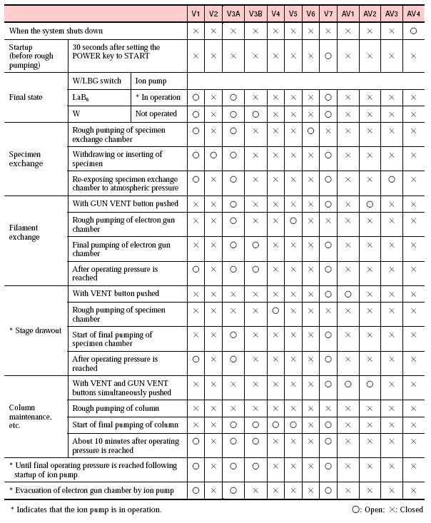
End of vacuum document.